Additional notes
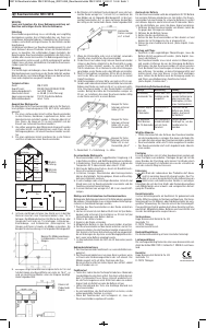
• Avoid temperature variations/damp rooms (Fig. D)
• Respect the minimum and maximum distances of the radio
modules from one another (Fig. F)
• Avoid placing near power-consuming equipment (Fig. G)
• Radio range and interference can be a ected by: Foil-coated
wool, aluminium foil, cladding, metallised window panes
(Fig. E)
Test/Maintenance
The radio module must be tested regularly to check its
functionality in accordance with the instructions for your smoke
detector. Press and hold the test key on the smoke detector
(for at least 20 seconds) until all the other networked detectors
have been triggered. Replace the battery if the smoke detector
indicates that the battery is empty. The battery life of the smoke
detector is reduced because the radio module and the smoke
detector share a battery.
Carry out regular functional tests in accordance with the
instructions for the smoke detector. Test the functionality
again if changes are made to the environmental
conditions (e.g. new fl oors, new or moved furniture,
lights, construction changes, etc.) and after replacing the
batteries.
Replace the module 10 years after installation.
Recycling instructions
This device must not be disposed of with unsorted house
hold waste. Owners of old devices are required by law to
dispose of this device correctly. Contact your town council
for further information.
Technical information
Supply voltage 9 V from smoke detector
Transmission frequency 433 MHz
Transmission mode send and receive
Radio transmission range approx. 25 m inside a house,
depending on surrounding area
Grouping 10-way
Measurements Ø 97 mm, height 22 mm
• Any code can be selected
• Set the 10-way code switch as necessary
Connection/Installation
Connect the smoke detector battery connection cable to the radio
module´s long battery connection cable (Fig. A5). The radio module
supplies the smoke detector with power. The red LED on the smoke
detector will fl ash every 45 seconds to indicate that the connection
has been correctly made. Insert the connected battery clips into the
smoke detector‘s battery compartment.
Insert the white plug of the radio module signal cable (Fig. A6)
into the underside of the smoke detector. Put the smoke detector
onto the radio module and turn the smoke detector in a clockwise
direction until it clicks into place. Make sure that the connecting cables
are on the side of the box so as not to impair the radio range. Fix the
smoke detector and radio module provisionally in the desired
position on the ceiling. To do this, refer to the installation instruc-
tions for the smoke detector.
Carry out a function test to check that all radio modules can receive
and send alarm signals. This is indicated by all the smoke detectors
in that particular group beeping loudly.
If the radio function test is successful, fi t the radio module fi rmly to
the ceiling using the smoke detector screws and fi ttings.
You may wish to make it di cult for the smoke detector to be
dismantled (tamper protection). To do so, remove one of the two
locking pins (Fig. A7) from the radio module housing base. If
the smoke detector is correctly clicked into position on the radio
module, you will be able to insert this locking pin into the hole created
on the side of the smoke detector. The smoke detector can then only be
dismounted from the radio module if the locking pin has been
removed using pliers.
The FSR 4160 radio module sends and receives alarm signals in
conjunction with the supplied smoke detector. It is designed for
domestic use or similar. As soon as the smoke detector emits an
alarm via the signal cable, the radio module sends the alarm to all
radio modules in its group that are within radio transmission range.
When the smoke detector alarm is no longer active, the radio
modules cancel the alarm after a few seconds and the smoke detectors
return to their normal operating state. Each radio module checks if
an alarm has been emitted every 13 - 15 seconds. The radio module
will only transmit radio signals in the event of an alarm. The FSR
4160 increases the safety of your home by relaying the alarm
signal by radio to remote parts of the house. This gives you valuable
seconds that could save your life and the lives of others around you.
Assembly
The radio module and the smoke detector share a battery which is
fi tted in the radio module (Fig. A1). If the battery is not inserted in
the radio module, the smoke detector cannot be mounted onto the
radio module. We recommend Ultralife U9VL Lithium batteries. Use
the radio module´s short battery connection cable (Fig. A2), which
is marked “To Battery”, to connect up the battery. The small red LED
(Fig. A3) will fl ash every 13 - 15 seconds to indicate that the battery
is fi tted correctly. The radio module is now ready to receive signals.
Programming the radio module
• The radio module is fi tted with a 10-way coding switch (Fig. A4)
for confi guring the group
• All radio modules that are intended to communicate with each
other need to be in the same group and thus have the same
setting as the 10-way coding switch. This would be the case, for
example, in a residential house (Fig. B)
• Radio modules in neighbouring fl ats/houses that are within range
must use another code to avoid neighbours being disturbed
by false alarms (Fig. C)
FSR 4160 radio module
NOTE: Gutkes GmbH hereby declares that the FSR 4160 product complies with the basic requirements and other relevant provisions
of Directive 1999/5/EC. The full text of the declaration of conformity can be found under www.gev.de
Technical and design features may be subject to change.
54
Gutkes GmbH
Rehkamp 13
30853 Langenhagen
Germany
Fax: +49 (0)511/95 85 805
www.gev.de
DGBFNLIESNDKFINRUSGRLVLTPLROSLOSKCZTRH


Liituge selle toote teemalise vestlusega
Siin saate jagada, mida arvate GEV FSR 4160 Suitsuandur kohta. Kui teil on küsimusi, lugege esmalt hoolikalt kasutusjuhendit. Kasutusjuhendit saab taotleda kasutades meie kontaktivormi.